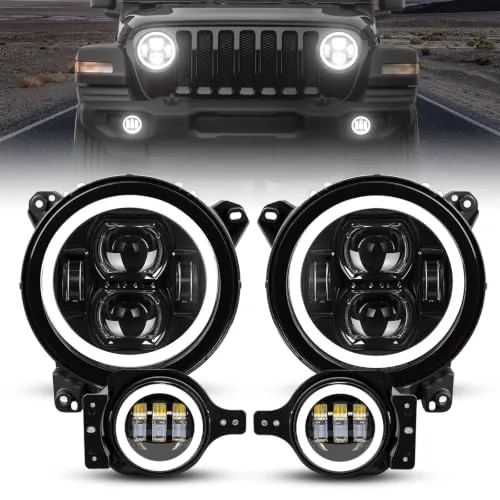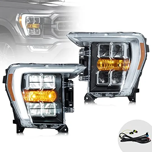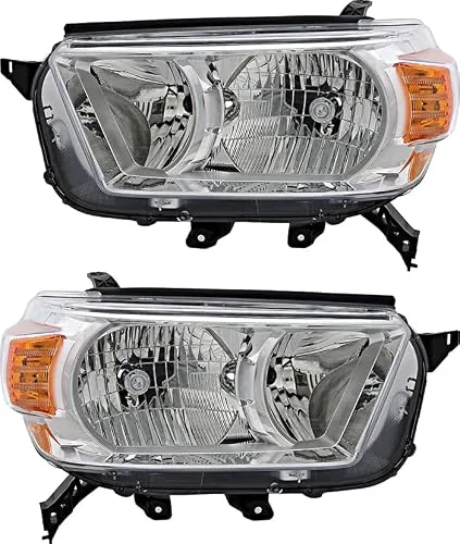
Ordering an aftermarket headlight housing without measuring first is one of the most common reasons returns happen. Even within the same make and model, trim variants, production year changes, and regional market differences can alter housing dimensions enough that a unit listed as compatible simply does not fit. Taking four measurements and checking two alignment details before you order eliminates that problem entirely.
What You Are Actually Measuring and Why It Matters
A headlight housing has three functional dimensions: the outer face width and height, the rear projection depth, and the mounting flange pattern. Sellers typically list only the first two, which is enough to confirm whether the unit will fill the opening in your bumper or fender but tells you nothing about whether it will clear the space behind the mounting surface. Rear projection depth is the measurement most buyers skip and the one most likely to cause fitment problems. On trucks and older SUVs with deep engine bays, there is usually clearance to spare, but on modern cars with tightly packaged front ends, an extra 15 to 20 millimeters of depth can put the housing in direct contact with a coolant line or wiring harness bracket. Measure from the front face of the opening to the first obstruction directly behind it. That number is your maximum allowable depth. The outer face dimensions matter for a different reason: they determine how much of the factory opening gets filled. A housing that is 5 millimeters narrower than the original will leave a visible gap against the grille or bumper filler panel. Take both measurements with a tape measure and confirm them with calipers on the two most critical faces.
How to Measure the Mounting Flange and Bolt Pattern
The mounting flange is the lip or bracket structure around the housing perimeter that presses against the vehicle body and accepts the fasteners. Its geometry has to match the original, not just approximately but precisely, because headlight housings align to within a millimeter of adjacent body panels. Start by counting the mounting points on the original housing. Common configurations are three-point and four-point, but some OEM housings use integrated clips combined with one or two bolts, and those clip slots have to match the aftermarket unit’s clip positions or the housing will flex at the unsecured edges. For each bolt hole, measure the center-to-center distance horizontally and vertically from a fixed reference point, typically the top-center hole or stud. Record these as an X/Y grid rather than individual spacing measurements; it makes cross-referencing the aftermarket spec sheet far easier. Also measure the flange width itself, the material strip between the outer edge of the housing and the bolt holes. A flange that is too narrow can crack under normal vibration, particularly on trucks. If the original housing has a rubber gasket channel along the flange, note its depth, since aftermarket units sometimes omit this detail and require a separately purchased seal to maintain weatherproofing.
Lens Angle, Projector Alignment, and Optical Centerline
On housings with projector-style optics, the angle of the lens relative to the mounting plane determines where the beam aims after installation. This is different from aim adjustment, which you do with the adjustment screws after the housing is bolted in. What you cannot correct with the adjustment screws is a housing whose optical centerline sits 20 millimeters higher or lower than the original. Measure the vertical distance from the mounting flange’s lower edge to the center of the projector lens on your existing housing. That number should match the aftermarket unit’s spec within 3 to 5 millimeters, or you will exhaust the range of the adjustment screws trying to compensate. For reflector-style housings the same principle applies to the bulb socket position. Measure from the flange to the center of the socket opening. A mismatch here creates hotspots or throws the beam pattern off-axis in ways that are difficult to diagnose after installation. Buyers upgrading from halogen to LED setups on vehicles like the Tacoma or F-150 often discover this issue only after installation (the Ford F-150 aftermarket headlight options reviewed on this site detail how optical centerline varies between OEM and common aftermarket replacements), so confirming this measurement before ordering saves a second round of work.
Connector Type, Plug Position, and Harness Reach
Housing dimensions get most of the attention, but connector compatibility is what determines whether the installation takes 30 minutes or requires splicing new piping into the harness. First, identify the bulb socket type on your existing housing. Common types are H11, H7, 9005, and H4, but vehicle-specific proprietary connectors appear on some OEM headlights, particularly on Japanese domestic market vehicles adapted for North American sale. Cross-reference the connector type against the aftermarket unit’s listed socket before ordering. Second, measure where the connector exits the housing: the position (top, bottom, rear-center, or offset) and the distance from the housing’s mounting flange to the connector. This tells you whether your existing wiring harness will reach the plug without strain. A connector that exits 60 millimeters from the flange on the OEM unit but 110 millimeters on the aftermarket unit may pull the harness tight enough to stress the connector pins over time. If you are also planning to change bulb types during this upgrade, checking current LED bulb compatibility guides before finalizing your housing choice saves a separate research step. The H4 LED headlight bulb guide outlines how bulb geometry affects socket fit in retrofit scenarios, which is directly relevant if your replacement housing accepts H4 inputs.
Four measurements cover the core fitment variables: outer face dimensions, rear projection depth, mounting flange bolt pattern, and optical centerline position. The connector exit location and plug type sit alongside those as a fifth check that is easy to confirm before ordering and difficult to fix after the fact. Cross-referencing your recorded measurements against the aftermarket unit’s published spec sheet, rather than relying on year/make/model compatibility filters alone, is what separates a clean installation from one that requires a return and second order. Measurements take about 15 minutes. A bad fit costs considerably more than that to resolve.
Affiliate Disclosure
This post contains affiliate links. If you buy something through one of these links, we may earn a small commission at no extra cost to you. We only recommend products and services we trust. Thank you for supporting this site!