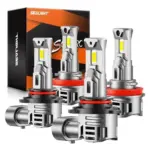
LED bulbs don’t run directly off a vehicle’s 12V or 14V charging rail the way halogens do. They require a driver circuit that converts the incoming voltage into a stable, regulated current, because LEDs are current-controlled devices, not voltage-controlled ones. Understanding what that circuit actually does explains why some automotive LED upgrades work cleanly and others flicker, overheat, or trigger warning codes.
What a Constant-Current Driver Actually Does
An LED’s forward voltage, the threshold at which it conducts and emits light, is relatively fixed for a given chip. For a typical white automotive LED, that sits between 2.9V and 3.5V depending on the junction temperature and the specific semiconductor compound. If you apply raw 13.8V from a running alternator directly to that chip, the current spikes, the junction heats instantly, and the LED fails within seconds.
A constant-current driver prevents that by acting as a feedback loop. It continuously samples the current flowing through the LED string and adjusts its own output to keep that current at the target value, commonly 350mA, 700mA, or 1A per channel depending on the bulb’s rated wattage. When supply voltage fluctuates, as it does in a car between cold cranking at around 10V and load-dump spikes that can briefly hit 16V or higher, the driver absorbs that variation and holds the LED current steady. The light output stays consistent because luminous flux from an LED tracks current, not voltage.
Buck, Boost, and Buck-Boost Topologies
The three main switching converter topologies used in automotive LED drivers each handle a different relationship between the input voltage and the LED string’s forward voltage requirement.
A buck converter steps voltage down. If the LED string needs 9V total and the car’s bus is at 13.8V, a buck topology is the efficient choice. It uses a switching transistor, an inductor, and a diode to chop the input and store energy in the inductor, releasing it at a lower average voltage. Efficiency typically runs between 88 and 94 percent in well-designed automotive buck drivers.
A boost converter does the opposite, stepping voltage up. This matters for single-LED applications or low-forward-voltage arrays where the string voltage is below the minimum bus voltage.
A buck-boost handles both cases and is common in multi-function bulbs like combination stop and tail units, where the driver must power different LED configurations at different brightness levels from the same supply. The tradeoff is slightly lower efficiency and greater circuit complexity, which shows up as a larger driver board inside the bulb housing.
PWM Dimming and Why It Creates Flicker Problems
Vehicle lighting systems often need to run LEDs at reduced output. Daytime running lights, for example, may operate at 25 to 50 percent brightness compared to the full headlight mode. The standard method is pulse-width modulation: the driver switches the LED current fully on and fully off at high frequency, and the duty cycle, the percentage of time the current is on, determines perceived brightness.
At frequencies above roughly 1,000Hz, human vision integrates the flicker and perceives steady light. Below that, particularly in the 50 to 200Hz range used by some OEM body control modules for DRL dimming, the switching becomes visible as strobing, especially in peripheral vision or when the eye tracks across the light source.
The frequency mismatch becomes a real issue in retrofit bulbs. The original circuit may have been designed around a halogen’s thermal inertia, which smoothed out low-frequency PWM naturally. An LED has essentially zero thermal inertia at the junction, so it responds to every pulse. Some aftermarket driver circuits include a smoothing stage that converts low-frequency PWM from the BCM into analog current modulation, which eliminates the flicker without altering the perceived brightness level (the H4 LED headlight upgrade options that handle this correctly are worth identifying before you buy).
Thermal Management and Why It Determines Lifespan
LED junction temperature is the single largest factor controlling both light output and longevity. At 25 degrees Celsius, a quality automotive LED chip might be rated for 50,000 hours. At 100 degrees Celsius junction temperature, that figure can drop below 15,000 hours, and color shift accelerates noticeably before outright failure.
The driver circuit contributes to the thermal problem in two ways. First, its own switching losses generate heat inside the bulb housing. A driver running at 90 percent efficiency dissipates 10 percent of input power as heat, which in a 20W bulb means 2W of additional thermal load in a space measured in cubic centimeters. Second, the driver must protect the LED from the heat that builds at the junction by implementing thermal foldback, a feedback mechanism that reduces drive current automatically as a thermistor reading climbs past a threshold, typically 80 to 100 degrees Celsius on the driver board.
Bulbs without thermal foldback maintain full brightness until the junction degrades, which looks fine in short tests but fails early in real-world use. Thermal foldback shows up as a slight brightness reduction during sustained operation, something that’s easy to mistake for underperformance but is actually the protection circuit working correctly. The same thermal engineering principles apply across LED products well outside the automotive sector, including grow lighting, where the LED driver circuit guide for grow tent setups covers junction temperature management in a comparable context. Proper heatsink coupling between the LED board and the outer housing is what makes foldback effective rather than a last resort.
Automotive LED driver circuits are doing real electrical engineering in a very small package: voltage conversion, current regulation, PWM handling, and thermal protection, all inside a housing designed to fit a standard bulb socket. When a retrofit LED bulb fails early or behaves erratically, the driver circuit is almost always the cause, whether from inadequate thermal protection, poor PWM compatibility with the vehicle’s BCM, or a switching topology that can’t handle the input voltage range. H13 LED headlight replacements that specify driver topology and thermal foldback thresholds in their documentation are the ones worth taking seriously.
Affiliate Disclosure
This post contains affiliate links. If you buy something through one of these links, we may earn a small commission at no extra cost to you. We only recommend products and services we trust. Thank you for supporting this site!